First-ever FDPSO at work on Azurite field development

Harry Howard, Ken Hampshire - Murphy Exploration and Production
Jeffrey Moore, Charles White, Ken Bayne - Doris Inc.
History was made in August 2009 when Murphy West Africa Ltd. began producing the Azurite field offshore Republic of Congo. Azurite uses the industry’s first Floating, Drilling, Production, Storage, and Offloading (FDPSO) vessel. While the FDPSO concept has been of interest for some time, Murphy West Africa and its contractor partners made the concept a reality. It is a robust concept with potential for broader applications as the number of pioneer deepwater discoveries shrinks and as the industry seeks new ways to monetize isolated fields.
Murphy West Africa and its contractor partners successfully demonstrated the viability of the FDPSO concept. The economic benefits of incorporating a drilling rig onboard an FPSO brings new hope for deepwater developments in similar environments.
The FDPSO concept also has application as an early production system. Drilling and production can begin to generate revenues while also generating valuable reservoir performance data.
The Azurite Marine field is in the Mer Profonde Sud (MPS) block offshore Congo, just north across the border from Cabinda block 14. Water depths across MPS range from 1,100 – 2,000 m (3,609 – 6,562 ft). Murphy West Africa Ltd. is operator with a 50% working interest. Other partners are PA Resources, 35%, and Societe Nationale des Petroles du Congo (SNPC), 15%.
Murphy discovered Azurite in January 2005 with the Azurite Marine-1 (AZRM-1) well. The field was appraised in late 2005 and early 2006 with the AZRM-2 and AZRM-3 wells. Each of the latter was sidetracked (ST) to appraise the four fault blocks of the field. AZRM-2ST was cored and tested. Aquifer strength was found to be essentially non-existent along the producing trend, necessitating water injection to support reservoir pressure.
Concepts considered
In March 2006, Doris Inc. was contracted as Murphy’s owner engineer for the Azurite field development. Doris formed the facilities engineering arm of Murphy’s integrated project team, and began to identify and evaluate field development alternatives, as well as to lead the capital project execution planning effort.
The four main alternatives evaluated were:
- 1. Subsea tiebacks to third party facilities
- 2. Subsea tieback to infield FPSO
- 3. Dry tree unit (DTU) producing to FPSO
- 4. Infield FDPSO.
A subsea tieback to third party facilities in Congo or Angola was deemed technically feasible, with the aid of subsea boosting. However, cross-border issues associated with tiebacks to third party facilities in Congo or Angola introduce too many schedule and political risks. Furthermore, subsea tiebacks to third party facilities did not meet Murphy’s objective to establish production operations in Congo. Hence, tiebacks to third-party facilities were rejected.
A subsea tieback to an infield FPSO is the “classic” solution for deepwater field developments offshore West Africa. However, strong demand for deepwater floaters exposed the project to significant schedule delays and floater day rates adversely impacted project economics.
DTU options were considered as a way to overcome the tight deepwater rig market. DTU was possible because the Azurite reservoir depth and areal extent permitted directional drilling from a single surface location. One alternative considered was a minimal wellhead facility with a tender assist drilling rig. This was successful at Murphy’s Kikeh field off Malaysia. Another alternative was a DTU with a self-contained compact drilling rig. In both cases, processing would occur on an FPSO in the field. Murphy rejected the minimal wellhead facility with tender assist rig option due to a lack of available tender rigs. The DTU with compact rig producing to an FPSO was retained as technically viable but cost-prohibitive.
Faced with deepwater rig shortages and the desire to make a step-change improvement in project economics, the project team conceived of the FDPSO alternative.
FDPSO feasibility
The FDPSO concept has “game changer” potential for deepwater field development, whether to lower the cost of development – even in a low oil price environment – or as an early production system. Because the concept has a compact drilling rig onboard, challenges regarding deepwater rig availability and day rates are eliminated.
Field development economics favor an FDPSO when reserves can be produced from a single location. However, the concept can work in fields with multiple drill centers. The FDPSO can sit over the drill center representing most of the field’s reserves, and other drill centers can tieback to it.

FDPSOs have been discussed and the concept developed in the marketplace since the 1990s. While it sounds novel, the technology involved is not new. Combined drilling and production platforms are common, as are deepwater drillships. Extending these time-tested concepts to drilling from an FPSO does not represent a quantum leap.
Both wet- and dry-tree FDPSOs have been studied. The Azurite team opted for a wet-tree solution because it is less of a technological step-out. With the wet-tree FDPSO, the moonpool is in the center of the vessel to minimize rig motions. A modular drilling rig base is installed. Wells are drilled from the vessel and completed subsea.
Drilling from an FDPSO requires spread mooring so it is most applicable to benign environments with prevailing seas from one direction. Motion studies for Azurite confirmed that the relatively benign and West Africa sea states, dominated by a long-period swell from the southwest, permitted drilling operations to continue even during a 10-year event.
An FDPSO concept hazard identification (HAZID) review was done prior to final consideration of the FDPSO as an acceptable option. The HAZID team included facilities engineers from the Azurite team, drilling engineering, and field supervisors from Murphy’s Kikeh Team, and drilling contractor HSE and engineering representatives. No high risks were identified that could not be mitigated through layout restrictions or use of specific operating procedures.
The Azurite project team developed detailed capex and opex estimates for the two short-listed options – the DTU with compact rig producing to an FPSO and the wet-tree FDPSO. The team quantitatively and qualitatively evaluated the two options applying a number of metrics such as capex, opex, operability, reliability, schedule, and risk.
The final recommendation in favor of the wet-tree FDPSO was vetted through an in-house peer review, with the team representing a cross-section of Murphy’s corporate experience and operations in the Gulf of Mexico, UK, and Malaysia.
As a final step, the concepts evaluated and the recommendation to develop Azurite using an FDPSO were presented to SNPC in 2006.
FDPSO systems description
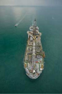
Hull
The vessel is a converted VLCC class tanker (M/T Europe), constructed in 1988. It has storage capacity of 1.4 MMbbl and a design field life of 15 years.
The vessel’s main propulsion system and associated equipment was retained to provide propulsion during the voyage from shipyard to site. The main propulsion system will be maintained in good working order, although there are no plans to use it during the lease period.
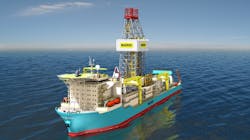
Topsides layout
The topsides embrace a traditional FPSO layout, where safety is the driving factor. Accommodations and safety equipment are at the stern, and the most hazardous materials and operations are furthest away, at the bow. Secondary to safety is a sensible layout for pipe routing, and to limit pipe runs as much as possible.
The drilling rig onboard poses unique layout constraints. The rig is amidships to minimize motions during drilling operations. Drilling modules were co-located and away from the production facilities, but within reach of an onboard 100-metric ton (110-ton) crane so they can be removed when drilling is complete.
Topsides capacities
The facilities are designed to the following capacities and specifications:
- Total fluids rate: 60,000 b/d
- Oil production rate: 40,000 b/d
- Produced water rate: 60,000 b/d
- Produced gas rate: 18 MMcf/d.
Oil
Production arrives via two risers. The crude is heated and the pressure reduced prior to reaching the inlet separator. From the inlet separator, the oil is heated again and the crude enters the LP separator. Gas from the separators is treated and used as fuel gas, with excess gas flared. Crude then flows to an electrostatic coalescer, where the remaining water is removed to meet export specification.
Crude is stored in tanks and maintained above the Wax Appearance Temperature (WAT) by steam coils. Oil is metered, and then transferred to shuttle tankers via transfer pumps and hose.
Gas and power
The FDPSO uses as much associated gas as possible and flares any remaining. Gas fuels the steam boilers for the main power generation. During late life when the associated gas rates have dropped, these boilers can run on marine grade diesel or heavy fuel oil.
Water injection
Treated seawater is injected under the following conditions:
- Seawater injection rate: 60,000 b/d
- WI pump discharge pressure: 2,500 psig
- Seawater filtration level: 98% of 2 microns
- Seawater oxygen content: < 10 ppb
- Provisions are made to install a Sulfate Reduction Unit (SRU) later, if required.
Mooring system
The mooring system is a 12-line, semi-taut, active system. Active mooring is required to maintain the position of the drilling rig directly over each subsea well. The mooring system limits vessel excursions to 2% of water depth of the FDPSO during drilling operations under 10-year storm conditions. Above 2%, the drilling riser is disconnected.
The mooring stoppers and tensioning system are monitored and adjusted during drilling and workover activities.
The mooring line components are synthetic rope with studless chain on each end. Suction pile anchors are employed due to the relatively soft soil conditions.
Mechanical handling
Azurite incorporates two onboard cranes, one rated at 100 metric tons (110 tons) and the other at 37 metric tons (40.8 tons). The 100-metric ton crane is heave-compensating. As mentioned, it can remove the drilling equipment, including the derrick, when drilling is complete.
Subsea structures were limited to 100 metric tons installed weight during the design phase to maximize use of this crane for subsea construction and periodic retrieval of subsea hardware. This allows the FDPSO to be more self-reliant and reduces of the requirement for multi-service vessels.
Offloading
Oil export is by shuttle tanker. Offloading is from the bow of the FDPSO through a single 20-in. (51-cm), 150-psi (1-MPa) working pressure floating hose that connects to the midships manifold of a shuttle tanker moored in tandem. The nominal offloading parcel size is 1 MMbbl. Crude oil is pumped using two cargo pumps, with a third pump on standby.
The shuttle tanker hawser connection has load monitoring and emergency quick-release hooks.
Drilling system
The drilling rig and rotary table are mounted on a substructure that straddles a 9-m x 7-m (29.5-ft x 23-ft) moonpool at an elevation of about 40 ft (12 m) above the main deck. The substructure also supports the tensioner system, which in turn supports the drilling riser.
Drilling riser configuration
A 16-in. (40.6-cm) OD high pressure-drilling riser is used for development drilling. The drilling riser is deployed through the moonpool. The drilling riser system consists of a Subsea Isolation Device (SID) at the base that connects to the subsea wellhead, a riser string made up with pin down x box up threaded connectors, a tensioning system, and a 10,000-psi BOP stack at the surface.
The riser accommodates a maximum shut-in pressure at surface of 5,000 psi and is designed to remain connected to the subsea wellheads in 100-year storm conditions.
Well control equipment
A surface BOP stack (SBOP), HP drilling riser, and SID are used rather than a conventional low-pressure marine riser and subsea BOP stack.
The SID consists of an upper and lower wellhead connector, ram BOP with two shearing blind rams, and an acoustically activated control system. The SID is run on the bottom of the HP drilling riser and lands on the subsea wellhead. The SID is not a well control device; it allows the well to be shut in at the seabed and to permit the HP riser to disconnect in an emergency. It provides a protective barrier and minimizes fluid escape from the well to the environment.
The SBOP stack consists of two pipe rams, one shear ram, and one annular BOP. The SBOP runs on a telescoping joint to accommodate FDPSO motions and draft changes.
Tensioners
The Drilling Riser Tensioner system (DRT) permits relative movement between the drilling riser and the FDPSO, while maintaining adequate tension at the top of the riser. The DRT accommodates motions of the FDPSO due to metocean conditions, as well as draught changes during production and offloading. The DRT is an active hydro-pneumatic type tensioner system.
The DRT system for the FDPSO consists of the following: drilling riser tensioners, idler sheaves, control panel, hydro-pneumatic cylinders, fluid-gas accumulator bottles, and instrumentation. The DRT connects to the pony structure and applies constant tension to the HP drilling riser system.
The HP drilling riser is used to drill and complete all wells at Azurite. During transit between wells, it may or may not be recovered for inspection or maintenance. The DRT allows for riser hang-off when the riser is not in use.
Removable drilling package
The drilling package on the Azurite FDPSO is a leased rig. The derrick is rated for 1.25 million lb hook load and 800,000 lb setback load during a 100-year storm.
The derrick and drilling equipment are designed for disassembly and removal after the drilling campaign is complete.
Frac spread
Murphy elected to install the frac spread onboard the FDPSO to reduce the schedule exposure associated with obtaining frac vessels in West Africa. The installed system is essentially the same as Schlumberger’s modular frac system recently installed on theBourbon Herald frac boat. It is capable of pumping up to 200,000 lb of proppant at rates of 30 b/m. The diesel powered frac pumps can deliver 8,800 hp. The system uses seawater and a liquid additive mix-on-the-fly process to avoid the additional storage requirements of conventional fluids.
Subsea systems architecture
The subsea architecture and layout is influenced heavily by the FDPSO concept, specifically by its drilling and workover capabilities, and the ability of its mooring system to move the FDPSO for direct vertical access to each tree. The hardware and trees are compactly grouped directly under the FDPSO to allow drilling and completion operations as well as maintenance and workovers. Trees are arranged in a polar array. This accommodates six production and three water injection trees, optimizes the distance between the trees in relation to the FDPSO horizontal movement capabilities, and to help standardize subsea components (e.g. well jumpers and flying leads).
Azurite has a single dual-purpose subsea manifold rated to 5,000 psig working pressure that supports both production and water injection. The manifold commingles produced fluids from production trees and transports it to the FDPSO via dual 8-in. (20-cm) flexible production risers. The manifold receives water from the FDPSO via a single 7-in. (17.8-cm) flexible water injection riser and distributes it to the water injection trees.
The flowline includes two production risers connected to an integral pigging loop in the subsea manifold to allow round-trip pigging to enhance operability and flexibility. Well testing is carried out by the method of subtraction, thus eliminating the need for a dedicated test line. All produced fluids are brought to the topside separators through two flexible production risers. One of the production risers is routed to the test separator and a baseline is established. The well to be tested is added to the production riser which is routed to the test separator. Well test data is obtained by subtracting the test results from the baseline. This technique is known as the method of subtraction.
Flow assurance
Reservoir modeling and flow assurance analysis of the wells at the Azurite drilling center indicated shut-in tubing pressure of approximately 4,300 psig and maximum flowing wellhead temperatures of approximately 250º F (121º C). Reservoir fluids analysis indicates a crude specific gravity of 25° API, a relatively low gas-to-oil ratio of 460 and a high wax appearance temperature of 129° F (54º C).
Steady state and transient flow assurance modeling was used to optimize flowline and riser sizes, determine insulation and artificial lift requirements to meet required arrival temperature and pressures throughout the life of the field, and to establish subsea operational procedures and mitigation strategies.
Analysis indicates that artificial lift will be required in late life as water cuts increase. Multiple gas lift options were analyzed, including downhole, manifold, and riser base gas scenarios. Ultimately, multi-phase pumping was selected rather than gas lift due to limited gas supply late in the field life, increased recoverable reserves with the MPP, and greater ability to mitigate risk associated with reservoir performance.
No-touch and cooldown times for the subsea components were established as part of the criteria for flow assurance analysis. A multi-pronged strategy of thermal insulation, methanol injection, blowdown, and dead oil circulation was defined to mitigate hydrate formation.
Trees
The Azurite Marine Development production and water injection subsea trees are vertical slimbore trees. The critical driver for tree selection was the use of a high-pressure slimbore riser with an outside diameter of 14 in. (35.5 cm). A survey of subsea tree vendors showed the only proven slimbore technology compatible with the high pressure slimbore riser is available in a vertical tree configuration.
The trees are rated for 10,000 psig working pressure, with a 5-in. (12.7-cm) nominal production/injection bore and a 2-in. (5-cm) nominal annulus bore.
The current drilling plan requires subsea trees for six production wells and four water injection wells. All production and injection tree designs use the same core components for ease of conversion, spares utilization, and storage.
Manifold
The manifold has the following characteristics:
- Six production and four water injection hubs
- Production from any well can be directed to either of the two production headers, thus permitting operation of a high and low pressure production system, if necessary
- A control system to operate valves, monitor pressure/temperature transducers, and pig sensors
- Interface for Steel Flying Leads (SFL) to deliver hydraulic fluid
- Suction pile foundation interface
- No provision is made for injecting chemicals directly into the production headers and branches of the manifold, as all injection takes place at the trees.
Distribution controls
The subsea control system is a multiplexed, electro-hydraulic system operating in an open loop configuration. While drill center proximity permits use of a direct hydraulic system, the electro-hydraulic system combines the optimum qualities of electrical (speed) and hydraulic (power) mechanisms to create a system that performs and endures for deepwater developments. The control system design is based on modular components with standardized connections to enhance serviceability along with manufacturing, logistics, and installation flexibility during project development. The modular building blocks are retrievable via the FDPSO, with common connection points permitting alternatives for intervention activities or system expansion if required. The system consists of three main sub-systems: topside control, subsea distribution, and subsea control. Real time monitoring is a requirement of the system.
Topsides production control
The Azurite topsides control equipment supplies the hydraulic power, conditions and regulates electrical power, and enables communication with the production system with the following:
- Uninterruptible Power Supply (UPS) supports the control system and allows controlled shut-down in case of a power failure at the host
- Hydraulic Power Unit (HPU) supplies redundant LP (5,000 psi) and HP (10,000 psi) supplies of water/glycol control fluid
- Master Control Station (MCS) is the access point for the control system. It communicates operator commands and receives system status updates for display
- Electrical Power Unit (EPU) conditions supplied electrical power, monitors status, and supplies overload protection to electrical conductors while relaying status to the MCS
- Topside Umbilical Termination Unit (TUTU) Connects and isolates between the umbilical and the topsides.
Subsea controls distribution
This equipment supplies the topside control equipment and hosts a method to relay command functions, supply utilities and chemicals subsea, while simultaneously transferring system status updates collected by sensors. The main artery of the distribution system is a multiple core umbilical routed from the topside host to terminate subsea. Components connect in series and parallel to form the distribution system. The following equipment forms the distribution sub-system:
- Electro-hydraulic umbilical transfers hydraulic power, electrical power, and electrical signal between topsides and subsea equipment. The assembly incorporates corrosion resistant metal tubes for all fluid circuits with redundant LP and HP hydraulic circuits. Individual injection circuits for each production tree allow metering from topside. The number of electrical conductors supports redundant electrical channels.
- The Umbilical Termination Assembly (UTA) is the main subsea distribution point for umbilical services. UTA terminates the subsea end of the umbilical and provides multiple access points to umbilical services and creates a handling point for installation. All access points for fluids, electrical power/signal use common installable/retrievable interfaces for each discipline (fluid/electric) with standard API ROV handles and operators.
- Subsea Distribution Unit (SDU) takes fluid from the umbilical, UTA, and interconnecting hardware and distributes it to multiple access points to support the overall well count and manifold requirements. The SDU as a whole is a retrievable intervention point for any umbilical anomaly or future requirements.
- Electrical Distribution Unit (EDU), like the SDU, supplies multiple access points for electrical power and signal services supplied by the umbilical through the UTA. The EDU supplies redundant power and signal channels to each tree. All access points for electrical power/signal within the EDU uses common installable/retrievable interfaces with standard API ROV handles and operators.
- Steel Flying Lead (SFL) connects the umbilical fluid access points, distribution points, and subsea trees and manifold. SFL, by its namesake, uses steel tubes (corrosion resistant material) as the basis of the design to transfer fluid from point to point.
- Electrical Flying Lead (EFL) connects umbilical electrical power and signal access points, distribution points, and subsea control modules on subsea trees and the manifold. EFLs transfer all power and data through a common pin and conductor design to eliminate installation and logistic issues.
Subsea control
This equipment provides monitoring and control interface to the equipment of the subsea production system. Sensors, actuators, and other devices transmit data and/or convert power to physical motion. Communication and control functions are managed by a designated Subsea Control Module (SCM). Each subsea tree and manifold contains a SCM which responds to all inquires and commands from the topside control equipment to fulfill the objectives of the operator.
Each SCM directs power and signal to the devices within its control. Software and electronics in the SCMs compile sensor data and system status information with unique addresses and time stamp validation to transmit to the topside MCS as requested. The SCMs use Directional Control Valves (DCV) to apply or vent hydraulic power to system valve actuators as directed from topside operators. SCMs have redundant electrical and fluid power supplies and fail-safe vent of valve functions upon loss of fluid supply. The SCMs are retrievable and interchangeable.
Subsea sensors are at multiple locations on the trees, manifold, and flowlines. These sensors transmit pressure and temperature as specified. The SCMs receive this information and relay topsides through the software. Critical transmitters (bore pressure, downhole pressure) are dual redundant; all transmitters work within the optimum range scale for that device.
Subsea chemical injection/metering
The chemical injection system consists of pumps with reservoirs located topside. Operation is monitored by the host control system. The subsea production control’s umbilical and distribution includes two designated chemical circuits (corrosion and scale inhibitors) for each production well along with bulk circuits for methanol injection. By incorporating these circuits in the distribution network, the need for subsea metering is eliminated. Metering for the required injected chemicals is provided between the topside termination of the umbilical and the outlet of the injection pump. Chemical injection rates are determined by taking samples of the production flow just prior to topside processing.
Flexible jumpers
Flexible well jumpers connect the production and water injection trees to the subsea manifold via vertical connectors. This system is used because flexible well jumpers offered synergies with the flexible flowline supply contract. In addition, the need for metrology was eliminated, thus simplifying installation activities.
Multi-phase pump
The MPP system comprises two multi-phase pumps in parallel, a pump module, piping, and support structure.
The MPP boosts the pressure of the produced fluid through two pumps in parallel, one for each flowline. The MPP is between the manifold and the production flowlines. The flowlines connect directly to the MPP, while flexible flowline jumpers connect the MPP to the subsea manifold.
The MPP skid is supported on the seabed by a suction pile foundation on a separate structure due to the size of the pump modules and related control system. The stringent skid level requirements dictated by the MPP vendor to ensure performance necessitated adoption of a unique leveling device mounted atop the suction pile.
The MPP is connected to a dedicated Power and Control Module (PCM) on the host facility via an umbilical containing power and communication conductors. Power is transferred via wet mateable connectors to the electrical pump motor.
Flowlines and risers
The range of movement required by the FDPSO to access each well requires the use of flexible risers. A flexible wave configuration was selected for the risers to allow for required movement of the host.
Because the drill center is directly underneath the FDPSO, flowline lengths are relatively short. Thus, from a contracting standpoint it made sense for the flowlines to be flexible.
Project execution
The Azurite project was internally sanctioned by Murphy management in December 2006. Contracts for supply of the FPSO and drilling package, flowlines, risers and umbilicals, subsea hardware and controls, and multi-phase pumps were competitively bid and signed in early 2007.
Murphy’s project management team and subsea facilities team remained Houston based, while the FDPSO facilities team relocated to Singapore to oversee contractor engineering and hull conversion, outfitting, and integration of the drilling packages. A small facilities team relocated to Paris to oversee subsea installation contractor engineering and field campaign planning activities.
Contractor engineering and fabrication activities continued throughout the remainder of 2007, all of 2008, and into 2009. Site installation activities began in October 2008 with installation of subsea foundations and manifold. A second installation campaign in early 2009 saw installation of flexible risers and umbilicals, as well as the FDPSO mooring lines. Sailaway of the completed FDPSO was February 2009. The vessel arrived onsite and mooring lines were attached in April 2009. FDPSO system commissioning activities commenced, followed shortly by the start of drilling. First oil was achieved on Aug. 9, 2009.
About the authors
Harry Howard is General Manager, Murphy Exploration and Production; Ken Hampshire is Asset Development Manager, Murphy Exploration and Production; Jeffrey Moore, P.E., is President of Doris Inc.; Charles White is Vice President, Doris Inc.; Ken Bayne is Capital Project Manager, Doris Inc.