Rod Edwards, Bud Hennessy, Brian Gallagher - BMT Scientific Marine Services
Monitoring structural integrity of underwater risers, and acquiring data suitable for improving their design, imposes numerous challenges on subsea strain sensors. The main goals for a strain sensor are reliability, long service life in deepwater, and accuracy, but these cannot be achieved without secure attachment to the pipe/riser wall.
In 2005, BMT engineered a strain sensor suitable for water depths up to 3,000 m (9,842 ft). Two of these permanent-type sensor assemblies are deployed and functioning satisfactorily since August last year at 100 m (328 ft) and 1,200 m (3,937 ft) below sea level on BP’s Greater Plutonio block 18 hybrid riser tower off Angola.
A program of tests is complete on a new clamp-on version of BMT’s subsea strain sensor. The sensor assembly can be installed in a few hours during J-lay or “handover” operations offshore on all types of rigid and flexible risers, riser towers, tendons, and other pipes destined for subsea operation. Individual sensors on the assembly can be replaced by a diver once installed.
The sensors feature an attachment that requires welded or forged anchor points on the pipe. While these intrusive anchoring devices can provide low hysteresis and high quality resolution, they are not ideal for fatigue-sensitive pipe sections.

To resolve this issue, BMT devised an alternative clamp-on subsea strain sensor to measure tension and bending strain on pipes and risers without employing forged or welded anchors, or risking removal of anti-corrosion coatings. The measurement process is simple, and involves measurement at several circumferential locations of the displacement between two well-defined points on the pipe surface.
Tests at the Structures Laboratory of the University of California at San Diego, and later in the US Navy’s high pressure cell in Port Hueneme, California, confirmed that the device was a robust and accurate tool, which is suitable for deployment in water depths up to 3,000 m (9,842 ft).
Each subsea strain sensor contains one custom-designed displacement sensor rated for direct exposure to high-pressure sea water for up to 10 years. It is housed in a secondary water barrier consisting of an oil-filled, pressure-balanced, corrosion-resistant alloy enclosure with dual bellows, which provides a low activation force and allows compensation for the high hydrostatic pressures associated with very deepwater.
For an installation where any significant bending moment is expected in addition to axial tension, a minimum of three sensors arranged around the circumference of a pipe provide valid estimates of the tension, magnitude, and direction of the bending moment vector. Additional sensors are recommended to provide redundancy.
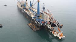
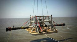
The clamping system anchors the ends of the measurement package and sets the system’s effective gauge length. The clamp is configured with proprietary features that facilitate a constant gauge length regardless of the curvature of the pipe. (A four-sensor ensemble is shown installed in a soon-to-be submerged tubular on a Gulf of Mexico spar).
The following calibration tests were conducted on the BMT clamp-on sensor:
- Cyclic (“zero return”) tests to 120% of full load and return, to establish zero repeatability
- Quasi-static stepwise load application with four repetitions of the loading cycle (standard load cell calibration tests)
- Oscillatory bending tests
- “Creep” tests to determine if the coating cold flow impairs the ability to measure the static bending moment.
Results from the zero return tests were comparable to results from conventional strain gauges. After being overloaded, the sensors returned to within ½ a microstrain (a stress of only 15 psi) at zero load.
The quasi-static stepwise calibration test results were surprisingly good for a mechanical system and can be seen in the BMT strain sensor versus strain gauge graph. The best fit straight line relating the bending moment derived from the direct measurement of strain and that derived from the BMT strain sensors is extremely linear, exhibits very little dispersion (uncertainty), and very low hysteresis.
To appreciate the comparison between the strains measured with conventional strain gauges on the pipe’s steel surface and the surface strain as estimated by the BMT strain sensor assembly clamped on the anti-corrosion coating, the strain sensor versus strain gauge data has been expanded.
This residual error plot clearly illustrates the performance of the clamped-on system. It shows the results of four successive tests where the load has increased in 10 steps from 0 to 30 kips (0-1,000 micro strain, 30,000 psi), before declining to zero load in a further 10 steps. The green dot denotes the starting point and the red the ending point. Both are within 0.2 micro strain - the level of performance that might be expected from a laboratory grade load cell. The most encouraging outcome of this test is that the envelope of all the errors lies between +/- 1.0 micro strain (one part in 1,000).
Finally a creep test was conducted during which the load was maintained constant for one hour. The clamp-on strain assembly on a 1 mm thick coating of fusion-bonded epoxy (FBE) exhibited no creep, in spite of the coating being stressed to a substantial fraction of the material’s yield strength.

Dynamic tests were performed during which the pipe was loaded with a sinusoidal moment at periods of 10, five, and two seconds. The relationship between the direct measured strain and the strain estimated from the BMT strain sensors remained within 2% of that for the quasi-static tests over the entire frequency range.
This May, BMT plans to deliver a riser integrity monitoring system, including 12 clamp-on subsea strain sensors, for two steel catenary risers (SCR) and two oil offloading lines to Saipem for Total’s deepwater Akpo development off Nigeria. Three clamp-on sensor assemblies also will be commissioned on two pull tubes and an SCR for a Gulf of Mexico spar.
For more information contact Rod Edwards ([email protected]) or Tas Abbasi ([email protected]).