Wayne Mueller, Norb Roobaert - Alliance Wood Group Engineering
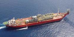
As global E&P moves to increasingly deeper waters and more remote locations, the FPSO vessel has become integral to field development considerations. The industry reports approximately 115 FPSO units currently in service worldwide, with more than 50 vessels under construction and a number at various stages of planning and design.
This demand for both converted carriers and newbuild vessels, coupled with record crude oil prices, has created the economic necessity to place additional units in service as quickly as possible. Standardizing topside production facilities can help.
Topside facilities provide onsite processing to convert raw production into marketable products and manageable by-products. The fluids from deepwater reservoirs hold a myriad of potential problems and often require complex treating facilities. The FPSO topside facilities are designed specifically to process the crude to meet the product specifications required for transportation and refining.
Standardized topsides benefits
Hydrocarbon reservoirs can vary with geographical locations and field characteristics. No two crudes are exactly alike, even though there are basic oil classifications – black oils, condensate, sweet, sour, etc. – that can dictate certain processing options. In addition to the oil property nuances, other factors such as payloads, metocean characteristics, and mooring patterns often impact topsides design. Despite the many influences, there are opportunities to create a facility with standardized layouts, components, and treatment options.
A “kit,” or comprehensive database of proven designs and layouts with uniform approaches to address most conditions and offers many advantages.
Cost effectiveness – Standardization gives a reference for a starting point during the conceptual and front-end design phases of the project. There is no need to “reinvent the wheel.” Rather, there is an opportunity to draw on an existing template that can be fine-tuned to fit the design basis at a cost savings.
Schedule improvement – Standardization accelerates the design process by using templates for process configuration, facility layout, and equipment arrangement. Predetermined module designs can accelerate other aspects of the project including procurement, fabrication, and commissioning.
Flexibility – A standardized kit of topsides process modules offers modular design options that can be used to satisfy known conditions.
Interchangeability – Often, module designs, equipment, and systems can be interchanged to meet specific requirements without affecting the overall facility function.
Scalability – A database of designs often allows components’ capacities to be scaled up or down to meet production requirements.
Expandability – Layout of the topsides can provide incorporation of future equipment needed as the field matures or for future tie-back of production that might not meet stand-alone economic hurdles.
Quality control – Designs in a kit would have been derived from those used on operating FPSOs. They would have been field-proven and can give a basis for future designs.
Safety – Standardized design modules would meet applicable safety standards and industry design practices, and can be tailored to meet operator requirements.
Experience contributes to standardization
The FPSO is complex. It requires many disciplines to engineer and design its topside facilities. Based on experience and using a design library, each discipline can contribute specific standardized approaches to accelerate the project and to offer the most benefits.
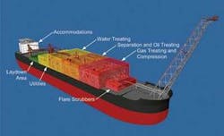
Layout and piping design: Layout of the topside facilities is driven by the sequential placement of the processing systems coupled with the safety policies imposed on production facilities. In addition, no single layout works for all combinations of processing facilities, vessel configurations, and metocean conditions. There are, however, common rules influencing the design that can be used to develop standardized configurations for most scenarios. The standardized layout generally facilitates integration of all disciplines and enables them to standardize as well.
The key to an optimal layout is modularization by process or utility system. Each major system is treated as a stand-alone system and as a modularized component of the entire facility. This concept will be the same regardless of facility type or capacity. Differences in equipment capacity or pressure ratings might alter the size of the modules, but will have minimal impact on layout.
Safety is most important in the topsides layout. Process modules are placed away from the quarters and control buildings. Only benign or non-hazardous equipment is located near the commonly occupied safe areas. This policy sets the tone for the overall configuration. More hazardous systems like gas compressors, production modules, and vents or flares usually are placed at one end of the facility. The remaining modules are placed in a sequential order following the steps of the treating process, which generally coincides with a decreasing level of risk.
The standardized layout uses a central corridor with modules on either side and pipe racks running from bow to stern. The piping interfaces between modules should be kept to a minimum. This configuration minimizes the impact of relative motion caused by wave action and resulting hog and sag of mid-ship bending. It also fosters personnel safety by allowing for access, egress, and the materials handling necessary for operation and maintenance.
Equipment-specific features also are incorporated into the standardized layout. Motion-sensitive separators like stabilizers and contactors typically are located near the ship’s center of motion to reduce the effects of motion on level control and the separation process. High-speed rotating equipment such as turbine-driven compressors and generators are aligned along the length of the FPSO. Large reciprocating compressors are placed with cylinders transverse to the ship, using the hull’s bulkheads to resist the compressor’s unbalanced forces and moments.
Another option for module configuration is to integrate the pipe rack into the module structure. This can reduce cost and time by eliminating the stand-alone pipe rack and reducing the number of piping connections. The piping is contained within the specific module with a basic in/out connection to the adjoining module to form a contiguous pipe rack once the modules are integrated.
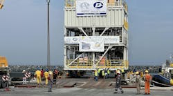
Modular systems, especially with the integrated pipe rack, simplify the overall shipyard process and reduce the integration cost and schedule. Moreover, the modules can be independently fabricated, tested, and delivered to the shipyard as complete packages ready for integration, commissioning, and start-up.
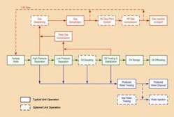
Process/mechanical: FPSOs can be used in gas fields, LPG, LNG, and other services. Historically, though, the majority produce oil in remote locations. Regardless of the location, the base case for standardization is producing an oil field through the typical separation and treating facility common to many FPSOs and production platforms. With standardization, however, comes the need to be able to easily adapt to various processing needs with simple adjustments or additions to the base case.
In the oil train, the standardized facility degasses and stabilizes the crude to meet vapor pressure requirements, typically designated in either Reid Vapor Pressure (RVP) or True Vapor Pressure (TVP). It also breaks any emulsion and removes associated water and sediment to meet basic sediment and water (BS&W) specifications.
When crude properties necessitate, additional treating equipment is incorporated into the design. Crude oil heating, desalting, sand or sulfur removal, and heavy oil dilution are such additions. The type of separation equipment, number of stages, and treating options depend on the fluid composition and liquid yield requirements.
In a gas train, the standardized facility recovers, dehydrates, and compresses associated and produced gas for either delivery or re-injection. Some compressed gas may be used as lift gas to enhance oil production. Where departing pipeline flow assurance issues require a reduction in the hydrocarbon dew point or when residual gas economics promote a Btu reduction by stripping heavier components, a hydrocarbon dew point control unit can be added. Several dew point control options exist. Each can be modularized and selected based upon performance characteristics and operator preference.
In addition to the typical sweet gas treating facilities, additional treating systems to handle sour gas (H2S) and/or acid gas (CO2) may be required. Again, these can be retrieved from the menu of options and plugged into the standardized kit.
The standardized design includes water treating and de-sanding. Water treating removes residual oil from produced water to enable disposal of the water by injection into a reservoir or release overboard. Sand is disposed separately. Several treatment systems exist and the chosen system resides in the water treating or process utility module.
When water injection pumps are needed to maintain reservoir pressure or dispose of produced water, a standardized pump configuration can be added to the system. When seawater is injected, a system will be required to treat and deoxygenate the seawater. As with the other systems, different seawater treatment processes are available. Once the unit is selected, it can be plugged into the overall design.
Structural: Whether the FPSO is a converted tanker or a purpose-built vessel, the topside structure must be supported by and work in unison with the floating vessel. The structural components of each module form both the shipping container and final support structure for the equipment.
The module will be subjected to transportation, installation, and operating loads. The base case and usual governing design condition for the module is the need to lift it onto the FPSO. The goal is to keep module weight under critical values to facilitate its installation by the shipyard’s quayside lifting device. If a module exceeds that limitation, a more expensive lifting method, such as a derrick barge may have to be employed. Alternatively, heavier modules have to be divided into smaller parts.
After the process and layout requirements have been determined, the framing of the individual modules becomes the principal structural initiative. The standardized design kit allows for flexibility in structural design. Each module structure generally starts from a similar concept but are all designed individually to meet the payload, space, and other unique needs of that particular application.
The standardized design is a trussed structure that provides a light, efficient system.
This offers the best starting approach, and the module can be readily altered with open bay framing to modify or move structural diagonals to accommodate or provide access to equipment.
Electrical: The size of the electrical system depends upon the overall capacity of the process system plus decisions regarding driver selection of major prime movers. These variables determine, in part, the size and number of generator trains and electrical modules needed.
Electrical equipment occupies a respectable portion of the overall facility area. Key decisions can enhance or detract from the standardized layout. One goal is to simplify electrical distribution by analyzing loads and systems to assess the tradeoff of longer lengths of large electrical cables versus adding additional electrical control buildings throughout the facility. While optimizing is a general engineering goal, providing an effective layout with a minimal number of electrical buildings to occupy space and integrate into process areas takes precedence in the standardized layout.
Depending on geographical location and classifying requirements, IEC or NEMA-ANSI ratings are used. These alternatives, while different in their certification methodology, do not necessarily affect or prohibit a standardized layout or module size. The classification chosen can, however, have an impact on equipment selection and availability depending on where it is sourced and where fabrication and integration takes place.
Instrumentation and control: Modularization of the topside facilities allows the instrumentation and control system itself to be modularized. The standard package allows the flexibility to integrate the latest technologies.
Typical configurations generally call for separate safety instrumented systems (SIS) and process control systems (PCS). An Ethernet system with remote input/output (I/O) minimizes weight and cabling costs, but other systems may be preferred and can be easily incorporated into the standardized design. Standardization provides a base case but also offers interchangeability of popular configurations from various suppliers to provide alternative systems.
One goal for the modularized control system is to pre-wire, test, and calibrate each module’s instrumentation and control system at its fabrication site prior to shipment to the shipyard for integration. This reduces the number of defects at integration and start up, and shortens the overall quayside integration and commissioning.
About the authors
Wayne Mueller is senior project manager at Alliance Wood Group Engineering and is involved in several FPSO projects. He also leads the company’s FPSO topsides standardization initiative. Mueller holds a BS degree in mechanical engineering from the University of Texas and an MS degree in petroleum engineering from the University of Houston. He has 16 years experience in project management and design experience, and is a member of the Society of Petroleum Engineers and the American Society of Mechanical Engineers.
Norb Roobaert, P.E. is president of Alliance Wood Group Engineering. He has more than 35 years experience in engineering and project management in the oil and gas industry. Roobaert holds degrees in chemical engineering and chemistry from the University of Michigan. He is a Registered Professional Engineer in the state of Texas and is a member of the Society of Petroleum Engineers, the American Institute of Chemical Engineers, and the Marine Technology Society.
Acknowledgement
The authors acknowledge technical contributions to this article from the following Alliance participants: Ricardo Abascal (Process Engineering), Bissudha Datta (Structural Engineering), Howard Newman (Facility Layout / Piping Design), Alan Phillips (Electrical Engineering), and Steve Smerek (Instrumentation and Control Engineering).
