Polyester mooring system makes debut with truss spar

Mad Dog reaches new ground in GoM
David Petruska, Hugh Wylie and Jeff Geyer; BP America Inc.
Saskia Rijtema; Heerema Marine Contractors
BP’s Mad Dog is the first truss spar to use a polyester mooring system. It is also the first to receive regulatory approval for use in the Gulf of Mexico from the US Coast Guard and the Minerals Management Service and the first permanent polyester mooring system to be installed in the GoM. With so many “firsts,” it is not surprising that BP and Heerema faced several challenges while installing the polyester mooring system.
It was important to the Mad Dog Project that the hull be fabricated and transported to the GoM as a single piece to control cost. The size and weight of the hull was already challenging the capabilities of the world’s heavy lift vessels, and in addition, payload was increasing to meet topsides requirements. These factors led the project team to investigate using a taut leg polyester mooring system. The base case was to use sheathed, steel spiral strand wire for the riser section of the mooring, but polyester offered the opportunity to reduce weight and improve mooring system performance.

Early design studies showed that a polyester mooring system could reduce vertical loads on the hull by 1,500-2,000 tonnes while also reducing offsets. The lower weight and the compliance offered by using polyester resulted in a lower pre-tension and maximum in-place loads than for an all steel system. It also resulted in smaller platform and ground chain as well as smaller chain jacks and fairleads, which produced cost savings beyond the impact on the hull. With these benefits weighed against the risk of using polyester, the project team endorsed the decision to proceed with a polyester mooring system.
Project overview
The Mad Dog spar is in Green Canyon block 826 in 1,348 m of water at the spar nominal position. The Sigsbee Escarpment lies just south of the spar and was a factor for laying out the mooring arrangement. Because the near surface geology just off the escarpment is highly variable, the intent was to minimize the number of suction embedded anchors in this region. These considerations led to a three-group mooring arrangement with one group having the foundations down in the escarpment.
The spar topside is designed to produce 80,000 b/d and 40 MMcf/d. The topside could be lifted as a single unit weighing approximately 7,000 tonnes. The spar’s operating weight is 16,820 tonnes, including a full API drilling rig. The truss spar hull lightship weight is about 19,000 tonnes with a diameter of 39 m, overall length of 169.2 m, and hard tank length of 74.7 m. Freeboard, once installed, is 15.2 m. The spar center well is designed for 13 top tension production risers and has one dedicated slot for the drilling riser. Oil is exported via a 610 mm steel catenary riser and gas via a 406 mm steel catenary riser through the Mardi Gras Transportation System.
To provide the installation contractor with the “ground rules” for installing the polyester mooring system, the project team prepared a specification of special considerations and requirements unique to handling and installing polyester based on API RP 2SM. The document describes the spar’s mooring equipment requirements along with the minimum installation engineering, planning, and documentation that must be performed.
Mad Dog’s mooring system is made up of 11 lines arranged in two groups of four lines each and one group of three lines. One group of four lines has the suction embedded anchor at the bottom of the Sigsbee Escarpment in approximately 1,660 m of water. The other two groups have anchors set at 1,300 m.
Each mooring line is composed of a suction embedded anchor, 146 mm of K4 studless pile chain, a BallGrab subsea mooring line connector, ground chain, either three or four segments of 270-mm polyester ropes of various lengths, one or two 13.1-m polyester test inserts, and 290 m of platform chain of the same size as the ground and pile chain. Steel thimbles inserted into the eye of the splice and H-link connectors connect the polyester rope segments.
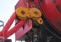
The project team elected to use a specially designed H-link for connecting polyester segments even though historically polyester was connected using elongated D-shackles and a few links of chain in between. This more compact design leads to a lesser overall weight for the connectors. The steel connectors in a mooring line can be 50-100% of the in-water weight of the combined polyester rope segments and can have an impact on the overall mooring performance. The H-link also offers some protection to the rope back eye of the splice during installation. The design team considered how to stop off the ropes through the H-link from the deepwater construction vessel (DCV) or an anchor-handling vessel (AHV), which led to two shackles being designed into the connector as handling aides. This feature also provided a means to recover a polyester rope segment for replacement or for test insert recovery.
Chain is an expensive part of the mooring system and adds a majority of the weight to a polyester mooring system, which negatively impacts performance. Clearly, it is desirable to limit the amount used. The platform chain length on Mad Dog was optimized, but required the following factors to be considered:
- Pay-out and pay-in requirements for offsetting the spar for well work and insert recovery
- Creep of the polyester over the service life
- Long-term construction stretch
- Manufacturing length tolerance
- Suction pile installation tolerance
- General contingency tolerance.
Similarly, designers took into consideration a number of factors in determining the ground chain length, including:
- Maximum spar offsets with consideration given to offsetting for well work and from the environment and the requirement that polyester cannot come in contact with the seafloor
- The possibility for additional creep or long-term construction stretch occurring during a design event and chain pay-in can-not occur until after the event
- Manufacturing length tolerance
- A margin for analysis imprecision and unknowns.
Most of these are straightforward to address, but the long-term creep and construction stretch was derived with help from Marlow Ropes and from test data.
Installation plan
For its cross project installation requirements, BP selected Heerema Marine Contractors (HMC) to install the hulls, moorings, risers, topsides, and pipelines for its five major deepwater GoM projects. For the Mad Dog hull and polyester mooring installation, HMC used the DCVBalder. This project marked the first installation of a polyester mooring system for the Balder, which also boasted the largest diameter polyester rope ever made for a mooring application. With guidance from the project installation specification, HMC developed an installation plan and manual covering all the necessary procedures to safely and successfully install the hull and mooring system.
To date, AHV have installed most if not all polyester systems, while AHVs and DCVs have installed spiral strand systems. However, the installation procedure could vary between an AHV and a DCV due to different equipment and capabilities.
Installing a polyester mooring system is similar in many ways to installing a sheathed, spiral strand wire system when using similar installation vessels, but a few differences do exist. For example, sheathed, spiral strands have special requirements on minimum bending radius and the associated tension to prevent damage to the sheathing and also to prevent kinking wire strands. Both have limitations on twist, although different, since spiral strand is not made torque balanced, while polyester ropes can be made torque neutral.
The polyester rope for this application was 270 mm in diameter. An equivalent spiral strand rope would be about 150 mm in diameter. Although the polyester weighs much less both in air and in water, it does take up more volume, which is an additional factor when laying things out on the transport barge and temporary storage on the DCV. This can also add some complexity to spooling.
HMC spooled the multi-layered rope from the transport reels under a very low tension onto the mooring line deployment winch (MLDW) in a single layer from which it was directly deployed over board.
HMC also provided information to rope manufacturer Marlow Ropes Ltd. to aid in designing the shipping reels so the reels could properly interface with HMCs MLDW and the spooling unit on theBalder. HMC and Marlow interfaced closely to share information about the rope design, understand the segment lengths each party would be working with during each phase of the project, and to ensure that all the different connecting hardware would fit together.
One of the first major decisions HMC made that would impact the installation plans was to pre-set a sufficient number of mooring lines to achieve a storm-safe mooring condition for the spar hull as soon as possible once it was upended. The hull and mooring designer had determined that three lines, one in each group, would achieve a storm safe mooring up to a 10-year Loop current or a winter storm event. Thus it was agreed to pre-set only one line per mooring group.
This decision and the unique issues associated with the polyester rope resulted in a number of installation considerations.
Since polyester ropes are not to come in contact with the seafloor, preset lines must be buoyed off at or near the seafloor. Surface buoys were selected because sub-surface buoys’ insufficient depth within the set boundaries created the risk of vessel collision. After the surface buoys were deployed, their respective positions were plotted on the positioning screen of the different vessels active in the field. Navigation aids were placed on the buoys.
During installation, the polyester ropes must also always maintain the minimum 5-tonne tension recommended in API RP 2SM. This, along with the following factors, determined the segment length for the pre-set mooring lines:
- Minimum amount of ground chain designed into the system
- Height of theBalder’s work deck and MLDW above the water line
- Maximum length of rope Marlow could produce due to road transport limitations
- +/-1% allowed manufacturing length tolerance on the polyester ropes
- Length extension in the polyester from change in load
- Environmental considerations.
Two polyester segments were pre-set in each line for the two shallower water mooring groups and three in the deeper water depth (i.e., a total of three lines pre-set representing seven segments of polyester). With these line lengths set, the remaining polyester segment lengths maximized flexibility while minimizing the impact on spares required.
Within the overall rope testing/qualification program, the project team gathered data to understand the stiffness and elongation characteristics of the rope under the loading conditions expected during installation. It was also necessary to understand the difference between the length of rope that Marlow would manufacture, the length of rope that the designer, Technip, specified for as-installed conditions at the prescribed pretension, and the length that could be expected during installation that HMC would have to work with. For these “first time loaded” ropes at the low loads typically seen during installation, a typical stiffness value was expected to be in the 8-10 x MBL range. This meant a length increase of a mooring line during the different installation stages of 50-100 m could be expected.
The next major area of planning was to develop procedures to keep the polyester off the seafloor during all phases of the installation. The spar itself must hold a certain position to prevent the polyester from touching the seabed. HMC elected to use a two-vessel operation once it started deploying the upper polyester segment. The second vessel was an AHV that would attach a work rope to the appropriate H-link to aid in supporting the polyester during this operation.
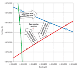
A 15-m minimum vertical clearance was maintained with the seafloor when determining the acceptable range of positions while also conservatively assuming all lines are 1% long, the maximum allowed per the project specification, and using a lower bound value on the polyester rope axial stiffness. In addition, an ROV continuously monitored the H- link that the AHV work wire was connected to, verifying position and exact depth. The ROV also provided a certain level of confirmation of the clearance and verification of the of the calculations. Special attention was paid to the “group 2” mooring lines, connected to suction piles in the escarpment, since any portion of the polyester mooring line rope could potentially make contact with the escarpment’s 15-20° slope.
Originally, the project installation specification did not allow any twist in the installed mooring lines. However, this is an extremely stringent criterion that would lead to more costly equipment and time-consuming operations. Thus the limit was relaxed to no more than 720° (two complete twists) per mooring line based on Marlow Ropes’ recommendation and work performed by Tension Technology Inc. (TTI), using its OptiRope program.
HMC developed twist management procedures to ensure the criterion was met. By virtue of the system design, any twist that found its way into the system should have undone itself when everything was free hanging down from theBalder’s deck up to the point when the subsea connector was mated. From that point forward, extra care was required to prevent twisting during the remaining installation steps. Twist was monitored by an ROV viewing a pre-painted stripe onto the mooring chain and a color stripe marker built into the polyester ropes jacket during the manufacturing process.
Common practice also requires that polyester never come into contact with sharp edges, high heat, or steel work wires. The MLDW pays out the rope directly overboard without passing over any surface.
In this case, the rope was stopped off at the H-link connectors, and the specially designed handling shackles on the H-link were used for any required rope handling. Should the jacket have been damaged in the field, work would have ceased while acceptable repair was effected.
Welding and flame cutting were not allowed in the vicinity of the rope either, so HMC and Marlow designed bolted clips for sea-fastening the rope reels to the transport cradles. HMC had Marlow make several Dyneema “soft” slings to handle the polyester ropes.
During the temporary storage phase, HMC made sure the lamiflex sheathing and tarps used for long-term storage and transportation were maintained in place and properly secured until just prior to needing a particular reel to limit the polyester ropes’ exposure to UV light and also possibility of foreign particle ingress.
Editor’s Note: This is a summary of Mad Dog Polyester Mooring Installation presented at DOT 2004.