Tarpon monotower develops further from 37 field applications
Cable-guyed system withstands elementsThere are now 37 cable-guyed caisson minimal production platforms operating now in the Gulf of Mexico, West Africa, and Indonesia. The cable-guyed caisson, known as the "Tarpon," was first used in 1987 and patents for the system are owned by Stolt Comex Seaway.
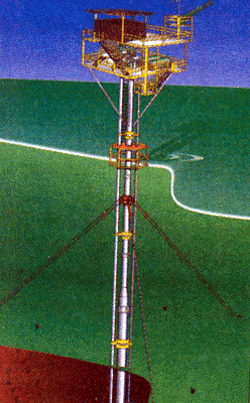
The Tarpon concept consists of a central caisson stabilized by three cable guys located about 120 degrees apart, composed of two cables each, pinned to an anchor pile at or below the mudline and pinned to the central caisson below the water. The anchor cables make an angle of about 35 degrees relative to the mudline. This results in the anchor piles being placed at a horizontal distance of approximately 170% of the water depth from the caisson. Since its inception, the concept has undergone three significant iterations:
- Original: Guyed with steel cables to underwater anchor piles through turning shoes (sheaves) located on the caisson below water with the cables fixed to the caisson above the water through tensioning devices.
- Intermediate: Similar to the first system, except the cables were composed of steel and synthetic fibre with the fiber segment transiting the wave/splash zone for corrosion mitigation.
- Present: Guyed to a termination clamp on the caisson located below water incorporating a proprietary rod and block system for hydraulic tensioning of the guys.
The present system eliminates the corrosion problem and the B-T fatigue concerns due to cyclic loadings at the sheave system. Cathodic protection is provided by sacrificial anodes on the caisson and anchor piles. The cable end connections are speltered with epoxy resins to avoid deterioration of these connections due to dissimilar metal corrosion. The core of the cables is bonded to the caisson and piles to provide electrical continuity.
History
The majority of the existing cable guyed systems are in the Gulf of Mexico. The remainder of these systems are offshore West Africa, and one system is assembled and awaiting installation in Indonesian waters. Over the last five years, installation of the caisson has mainly been by the drilling rig, with additional wells being drilled subsequent to the caisson being installed. At these locations, the anchor piles and guy cables were installed by a separate construction vessel, without interfering with this drilling phase.SCS has a stock program for the guyed caisson. This program provides all the components necessary to assemble systems in 150 ft, 200 ft, and 250 ft of water depth for API 2A Gulf of Mexico environmental criteria utilizing poor soil. Enough components are stocked to assemble any two of the three designs.
About 45 days are required from the provision of site-specific soil information to delivery. The last three systems were delivered from this program. The operator installed the first complete system with deck and helideck adjacent to a mud-line suspended well while waiting on rig availability, and they subsequently moved a rig onto the site for additional drilling. The second system, required ocean freighting of the components and assembly in Indonesia to meet specified schedules.
The third system currently being assembled, will require assembly of the caisson for installation in just 30 days, while the well is being drilled and will be installed from the drill rig once the well is tested and completed. Because of the conservatism of the stock design this caisson will free-stand for about six months while the deck and guying system are being fabricated and installed. This eliminates the requirement for a second mobilization of the drill rig to tieback the well and minimizes dry hole cost while still maximizing cash flow.
The stock system design results in greater conservatism and somewhat higher cost than a site-specific design, but the increased cost is usually offset by early production and accelerated cash flow.
Differentiation
The cable-guyed caisson is a quasi-compliant structure whose behavior and motion is governed by the tension in the guy system and the deck mass. The greater the pretension load in the guys, the more linear the cable spring system becomes which lowers the natural period of the platform, resulting in smaller deflections and improved fatigue life.The cost for this increased functionality are larger cables, larger diameter anchor piles, and in most cases, longer anchor piles. Pretension of the cables is a matter of design and is a balance between fatigue life and the human response to motion from the structure. Natural periods for existing systems vary from 2 sec. to 3.5 sec., with one installation in 218 ft of water with a deckload of 350+ short tons, having a measured period of 4.2 sec.
Because of the relatively wide spread of the anchor piles, the guyed caisson enjoys a larger lateral load capacity than do braced systems. This capacity provides greater reserve strength over a braced system and results in lower cost for water depths exceeding 120 ft. In water depths less than 120 feet, the system geometry allows 360 degree access by lift boats for servicing wells. This access radius is limited in the braced caisson and tripod alternate designs.
A guy system can be retrofitted to existing caissons or flare towers to reduce motion, which affects operations, and/or to improve fatigue life in areas where service lives exceed the original estimated lives.
Project differences
The caisson and guying system are conservatively designed as confirmed by peer reviews and by certifying agencies. The maximum loads in the caisson and cables occur when the design event maximum environmental load is at 90 degrees to one of the guy cables. The design assumes this to be the case regardless of guying system orientation.Additionally, of the cable pairs with maximum load, one cable is assumed to carry the entire load during the design event. The offside tension is assumed to remain effective. No shielding is considered for appurtenances. Trapped masses are accounted for in the dynamics but offer no structural strength. And, amplification is considered in the environmental loading. As a consequence, these clone-like characteristics lead to short structural design times and lower end cost due to standardization of components.
For caissons in cyclonic areas, a minimum diameter of 48-in. is considered appropriate. This normally provides support for one internal well and/or one external well. For D/t (outside diameter/wall thickness) ratios greater than 30 (1.50 in. for 48in. diameter), Class C material can be utilized (ASTM A-36). As a minimal structure, the combined stress unity ratios are limited to 0.90 or less for the caisson by API RP 2A. Caisson penetration depends on soil properties and deck operating loads, and is in the range of 100-130 ft for most existing installations.
Terminations
The termination of the guy cables at the caisson is a pinned connection to either a padeye clamp or sleeve. The vertical component of the cable force at the clamp is downward. Existing systems either utilize a structural tie to the boat landing where the weldment of the landing to caisson transfers the force to the caisson, or a stop ring welded to the caisson below the clamp, to resist the vertical component.Friction between the clamp and the caisson is not considered effective in the design. The padeye material is API 2H 50 ksi for stress and fatigue-consideration and the pins are 80 ksi alloy material to minimize size since they are diver installed. The termination clamp is set at least 12 ft below mean ebb water (MEW) to provide clearance for boat traffic. In non-cyclonic areas, the clamp is set 17-27 ft below MEW for most efficient caisson design.
In cyclonic areas, a 6-strand steel cable, manufactured to API Specification 9A, is used in the tendons. Construction classification is design dependent, but 2-in., 6 by 19 cable is considered a minimum size. Cables are designed to 50% of nominal breaking strength, in accordance with API 9A, with one of the cables being ineffective (broken/missing). Cable properties for design correspond to recommended values in API RP 2SK (1996).
Fatigue life
Fatigue life of the system is a prerogative of the owner but is generally three times the anticipated service life as a minimum. Fatigue analysis, based on spectral wave data, is used to determine cumulative damage. Joint geometry is used to determine appropriate stress concentration factors and S-N curves (API: AWS; DnV; DEn) are used to determine fatigue life. More stringent criteria is applied to caisson field weldments (welded one side only).The lack of TKY joints in this design allow the use of Grade C material in the major components simplifying welding procedures and resulting in shorter fabrication times. Through-thickness and higher yield material is utilized in the termination at the caisson. These termination devices are usually available as stocked items. Because of the simple geometry, NDE services can be utilized without the necessity of stoppage in the assembly resulting in further savings.
The caisson can be installed by the drill rig and the guying system placed by a work vessel without removal of the rig, resulting in savings in overall rig time, elimination of temporary plug and abandons, mudline suspension equipment, and additional rig mobilizations. This allows additional drilling, completions and testing which, with planning, leads to early cash flow enhancing economics of marginal properties.
With commitment by the operator to fabricate the caisson prior to spudding a well, a period of 15 days from rig move-off to production has been attained. Utilizing a stock system, a period from logging to first production of 60 days has been attained.
The most favorable economics result with two or three-well programs and caisson installation before rig move-off. The system is adequate as a substructure for producing facilities in the 60 MMcfd gas or 10,000 b/d. Reciprocating compression has been successfully employed on a guyed-caisson system in over 200 ft of water.
Commercial differences
The cable-guyed caisson system has many characteristics that distinguish it from other conventional structures as follows:- Repeatable design with requirement of inputting key data on proven programs yielding rapid generation of site-specific design.
- Following site-specific analysis, AutoCAD drawings already standardized, can be developed quickly.
- Flexibility of the structure allows SCS to stock a minimum number of components, thus enabling us to deliver structures in 150 ft, 200 ft, or 250-ft water depth on a fast-track basis.
- Simple fabrication techniques with use of standard materials.
- Availability of the caisson during appraisal phase and rapid mobilization.
- For water depths greater than 150 ft and less than 300 ft, a minimal structure yields significant cost savings, compared to tripod and 4-leg jackets.
- After initial re-tensioning (6 months), the structure has proven to be a particularly low maintenance cost entity.
Copyright 1999 Oil & Gas Journal. All Rights Reserved.