Non-chemical products offer effective flow assurance solutions
Keshawa Shukla
McDermott
Recent technological developments of non-chemical solutions can be applied to manage flow assurance challenges to ensure transport of oil and gas from wells to onshore facilities throughout the field life safely and economically. A combination of different non-chemical solutions can reduce capex and opex significantly and minimize/avoid injection of chemicals, thereby reducing maintenance costs.
The goal here is to present a brief overview of latest developments in non-chemical solutions for managing flow assurance challenges.
Flow assurance review
The oil and gas industry has had enormous success in the flow assurance arena over the past decade. Past experiences from subsea field developments have enabled engineers to be more cost-effective in design and operation. Still, flow assurance remains one of the key technical challenges operators face in deepwater.
The most challenging flow assurance issues are the management of wax, hydrate, asphaltene, emulsion/foaming/scale, slugging and pigging. As water depth increases, issues related to multi-phase flow, production chemistry, pipeline integrity, subsea and surface operations are magnified.
For instance, at the low temperatures of subsea conditions, heavy hydrocarbons may precipitate as wax and asphaltene, and mixing of hydrocarbon fluid and water may form hydrate restricting the flow. During shutdown of a subsea pipeline wax/gel may form and solidify when a crude oil cools below its pour point.
Under high pressure conditions, high CO2 and H2S contents in production fluid with water can lead to corrosion. Under high pressure and temperature conditions the relatively large amount of produced water may form scales. Sand production from formation can cause erosion in a subsea pipeline.
At turndown flowing scenarios, liquid build up at a production riser base can cause severe slugging and separation problems in equipment lacking insufficient backpressure. All these issues can cause operational problems from downhole to processing facilities.
In recent years, flow assurance has combined multi-phase flow and production chemistry to manage the interface between reservoir and topsides processing, and is not only based on hydrates, wax, scale, asphaltenes, and corrosion, but also includes network modeling and transient multi-phase simulation to answer the operability of the designed facility and risk management.
Therefore, the subsea systems should be properly designed in a cost-effective way taking into account the above factors starting from concept selection through detailed design of subsea field development. The effective preservation of fluid heat in pipeline systems is one of the most important design parameters, especially for preventing wax and hydrate solid formations/depositions.
Overview of non-chemical solutions
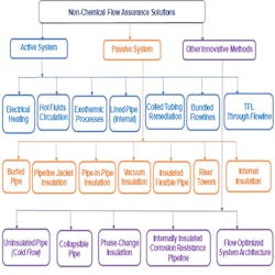
The experience of non-chemical solutions and innovative technology is encouraging. Several non-chemical solutions products and approaches are now available which can be applied to deepwater and ultra-deepwater field developments. The poster also includes properties of non-chemical materials, their recent subsea applications and vendor information. Based on the survey, the available non-chemical solutions can be classified in three categories, 1) active system, 2) passive system and 3) other innovative methods. A brief account of these systems is given below.
Active systems. These include electrical heating, hot fluid circulation, exothermic processes, line pipe (internal), coiled tubing, bundled pipelines, and through flowlines (TFL). They require input of energy in the form of work or heat. The important characteristics of active systems are the power requirement, circulation fluid types, frequency or continuous usage, increase temperature/pressure and offset distance. For instance, direct or indirect electrical heating requires energy in the form of electric current to supply heat to a pipe wall. Hot fluid circulation requires heat to elevate temperature of the circulating fluid and work to pump the fluid through the pipeline. The opex for active systems can be offset by reducing the operating costs required to keep production fluid out of hydrate or wax conditions during shutdown operations. Active heating can remediate hydrate plugs safely and can remediate blockages in hours.
Passive systems. These include buried pipe, pipeline wet insulation, pipe-in-pipe (PIP) dry insulation, vacuum insulation, insulated flexible pipe, riser towers, and internal insulation. They do not require an input of energy such as work or heat. Heat retention is achieved by surrounding the pipeline with materials that offer a high resistance to heat transfer with low thermal conductivity. The important characteristics of passive systems are the physical properties such as thermal conductivity, coating thickness, U-value, heat capacity, and density of materials. For instance, thermal insulation systems are wet insulation, dry (pipe-in-pipe) insulation, and pipeline burial. Flexible pipes can be insulated, but their outside diameter is intrinsically large and limits the amount of required insulation. Costs for passive insulation systems involve capex. A combination of pipeline wet insulation, burial, and trenching can provide a cost effective passive system. The insulation system can impact on-bottom stability, cost of installation and field-joint design. Riser insulation may impact fatigue.
Wet insulation. There are now several advanced wet insulation materials available for different subsea applications, such as solid polymers polypropylene (PP), novolastic, polyurethane, and syntactic foams glass syntactic polyurethane (GSPU). They can achieve low U-value for heat retention in subsea flowline systems including jumpers and hardware. The wet insulation is directly coated to steel pipes and placed on the seabed exposed to seawater. It is typically tailored to withstand compression due to hydrostatic head in deepwater. It offers good mechanical properties along with an extended track record in the offshore oil and gas industry. Wet insulations are available in several forms, such as 3-layer, 5-layer, and 7-layer consisting of FBE, adhesive foam PP, insulation materials, and an outer shield.
Pipe-in-pipe (PIP) insulation. For heavy oil production, PIP insulation can provide better heat retention to maintain fluid temperature above the safety margin of hydrate and wax temperatures during normal operation achieving lower U-Values (~ 1.0 W/m2-K or less) and high insulation performance. It also offers a significant reduction to both material and installation costs. Such insulations have been tested at deepwater depths. In PIP, a pipe is inserted inside another pipe. The created intermediate annulus is used to place a dry insulation material which is protected by the outer pipe from hydrostatic pressure and water penetration. In PIP insulation, the inner (carrier) pipe is insulated with a low conductivity dry insulation such as aerogel or low density polyurethane foam. The outer pipe is typically steel or polyethylene depending on applications. In case a rigid outer pipe is requirement, an air gap exists between the outside diameter surface of the insulation and inside diameter of the outer pipe. The effective conductivity of the air gap is reasonably low and adds to the heat resistance of the system.
Other innovative methods. Other technological advances to address flow assurance problems include: cold flow technology for un-insulated pipe, collapsible pipe, coiled tubing remediation, phase change insulation, internally insulated corrosion resistance pipeline, and flow optimized system architecture with limited applications.
Cold spot management in PIP flowline system with water stop and equipment
The subsea flowline and structure/equipment must be insulated adequately to meet design, fabrication, and operational requirements. The purpose here is to investigate the effect of un-insulated or partially insulated subsea structures/equipment on the operating temperature of an example production system, and how the insulation can prevent cold spots to maintain fluid temperature above hydrate and wax temperatures and achieve required cool down time for normal and shutdown operations.
A typical Gulf of Mexico subsea production system consists of four manifolds (MF1 with 2 wells, each MF2, MF3 and MF4 with 1 well) including jumpers, flowline, gas lift-riser base (GLRB) and riser leading to a FPSO. The flowline length is approximately 17 km. Wellheads are in water depth of 1,430 m, with seabed temperatures below 3.2°C. A flowline system consists of (8-in. x 12-in.) PIP flowline (18.3 m steel, 15 mm aerogel, 18.3 mm air, 19.1 mm steel and 3 mm 3LPE) and 7-in. flexible riser. All 8-in. jumpers are insulated using 3.5-in. GSPU wet insulation. The fluid comprises of heavy oil, water, and gas prone to hydrate and wax formations, with 33° API. The above configuration yields U-Value of approximately 1.0 W/m2-K for PIP flowline, 3.5 W/m2-K for flexible riser, and 2.9 W/m2-K for jumpers. The water stop and equipment at the manifolds and GLRB directly exposed to water are also considered.
The assumed design and operation constraints are:
- Early life fluid with maximum production rate
- Cool down time requirement of 12 hours (including no-touch time) for shut-in operation using pour point (18°C) to prevent wax deposition/gelling
- Here a transient multi-phase OLGA model (1D model without axial heat transfer) is used to study two scenarios as discussed below
- However, a 3D computational fluid dynamics model can be used to assess the effect of detailed fluid flow including axial heat transfer in subsea structures.
Case 1- Cold spot in PIP flowline/flexible riser system
During normal operations, the fluid temperature in the PIP flowline remains above wax appearance temperature (WAT) (29°C), pour point (18°C), and hydrate temperature. During shut-in operations, the fluid temperature is above 18°C for both 8-hour and 12-hour shutdowns. However, the fluid cools below the pour point and hydrate temperature for 24-hour shutdown. The flowline yields a cool down time of 12 hours. Therefore, the above PIP insulation is adequate to prevent low temperature problems due to cold spots for normal and 12-hour shutdown operations, and provides sufficient cool down time to commence wax and hydrate remediation during shutdown operations.
Case 2: Cold spot in flowline/riser system with water stop and equipment
In this case, the PIP flowline/flexible riser system of Case 1 is assumed to include water stop seal assembly and subsea equipment at manifolds and GLRB. Such structures are commonly encountered in subsea field development.
Water stop assembly isolates a section of flooded annulus by preventing water passage to the adjacent PIP sections during installation and normal operations. The middle steel section of water stop does not touch the carrier pipe during normal operations unless water stop is activated in any flowline section. The water stops were placed at 700 m intervals of PIP flowline assuming concentric layers surrounding the flowline with three segments of equal length/thickness, 219.1 mm/33.3 mm (annular gap between inner and outer pipes). The water stop combines properties of rubber (HNBR) and steel (segment layers: inner pipe CS/CS/HNBR/outer pipe CS/3LPE).
Typical subsea hardware and equipment were added to the transient model to assess the impact of cold spots on temperature due to equipment (valves), which are insulated up to the bonnet but un-insulated on the actuator and pressure transmitters. The un-insulated valve section is accounted for by inserting a section of pipe with equivalent length of the valve bonnet diameter into the subsea hardware piping. The un-insulated subsea valve accumulators and pressure transmitters are modeled as cylindrical pipe segments. All equipment valves are placed on the main flowline. The insulated sections of the equipment are insulated using 3.5-in. GSPU.
The water stop seals and subsea equipment at manifolds/GLRB can cause cold spots in the subsea PIP flowline due to their inadequate insulation and can yield much lower temperatures than the normal operating temperature. Consequently, the minimum operating temperatures at the cold spots may lie in hydrate and wax/gel formation regions, and required cool down time of 12 hours may not be achieved for shutdown operations.
U-Value at water stop and equipment locations yield much higher U-Values (> 50 W/m2.K for water stop, and > 200 W/m2.K for equipment) than those of PIP flowlines leading to cold spots at those locations. The sections of PIP flowline near and at locations of un-insulated equipment cool faster. However, the cold spots are not seen during normal operations because only a small portion of the equipment is un-insulated and sufficient retention of heat is still maintained. For 8-hour shutdown the minimum fluid temperature in the system is approximately 19°C, which is slightly above the pour point. However, for 12-hour shutdown the flowline operating conditions lie in the wax gelling and hydrate regions. Due to the inadequate insulation of subsea hardware, the cold spots appear to yield less than 12 hours of cool down time, which is insufficient for operators to take remedial actions, especially for unplanned shutdowns.
Conclusions
Non-chemical solutions can be applied safely in thermal management of hydrate and wax problems for subsea field developments. When the flowline production system including water stops and subsea hardware are not insulated adequately, cold spots may lower the temperature substantially and enhance the risks of hydrate and wax formations/depositions. Application of PIP insulation combined with wet insulation can prevent such risks effectively and reduce capex/opex by minimizing the use of chemical inhibition, pigging frequency and depressurization. Even in PIP flowline/flexible riser production systems all subsea jumpers, structures, equipment and water stop assembly involved should be insulated adequately to maintain fluid temperature above the hydrate and wax formation temperatures. The combination of chemical inhibition, depressurization, pigging, and dead oil circulation can help reduce opex for economical operation of the subsea production system throughout the life of field.
The author
Keshawa Shukla, Ph.D., is senior manager of flow assurance engineering and global subject matter expert at McDermott in Houston, Texas.
Acknowledgment
The author wishes to acknowledge the McDermott business development teams in Houston and London, and the subsea engineering group for supporting this publication. Special thanks go to Miranda Smith and Jason Martinez.