Jeremy Beckman
Editor, Europe
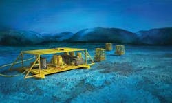
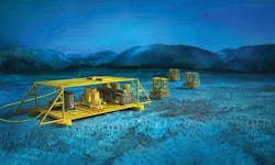
Siemens is close to completing an initial test program on the four main components (subsea transformer, subsea medium-voltage (MV) Switchgear, subsea variable speed drive, and subsea power control and communication system) of a proposed subsea power distribution hub. The Subsea Power Grid will be connected on the seafloor to the array of new equipment emerging for subsea production, processing and boosting. This should facilitate expansion of field development into deeper water, longer step-outs, and more demanding production environments.
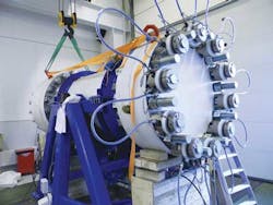
Design of the grid's subsea transformer, switchgear and variable-speed drives (VSDs), as well as the communication and control system started in 2010. The subsequent engineering/test campaign has been conducted mainly at Siemens' Subsea Technology Center in Trondheim, Norway, since it was opened in September 2011, in co-operation with Siemens locations in other countries. The 10,000-sq m (107,639-sq ft) facility in Trondheim includes a pressure test laboratory that can simulate ultra-deepwater conditions (up to 460 bar/6,672 psi) in 23 pressure vessels of different sizes. Initial testing of the individual Subsea Power Grid (SPG) component prototypes is nearing completion, and will be followed next year by extended shallow-water trials of the integrated SPG in Trondheim harbor. One of the goals is to ensure that the system can remain in operation on the seafloor for many years, without maintenance.
The development, testing, and qualification program is supported by Chevron, ExxonMobil, Petrobras, and Statoil, all noted for pushing the boundaries of subsea and deepwater production. The technologies they and other operators are looking to transfer to the seabed include gas compression, water injection, multi-phase booster pumps, and subsea separation. According to Subsea Technology Center director Jan Erik Lystad, "oil companies have been telling us that they need more power to be distributed to multiple subsea consumers in order to reach out further to access more reservoir pockets."
"Current technology can transmit only limited amounts of power to the seabed, which does not allow connections to multiple equipment items, or 'consumers,' in an effective manner," Lystad explained. "When each subsea consumer has to be connected to topside power distribution equipment via individual subsea cables this requires a lot of topside space and riser capacity. That makes the operation both complex and costly, and it is not a viable solution for long step-outs, for a large number of consumers, or for high-power requirements."
"By implementing a subsea power hub and grid, operators of subsea fields will be able to distribute power more widely," Lystad noted. "In addition, the subsea power supply and distribution system eliminates a lot of complexity. With the Subsea Power Grid, there is just one high voltage (typically up to 100 kV) cable running from the surface to the seabed to a subsea step-down transformer in the hub, where voltage will be reduced to 36 kV. Then the power is distributed through a medium-voltage switchgear (one switch per consumer) and on to individual variable-speed drives for each pump, compressor, and so on."
In addition to reducing cable volume, the Subsea Power Grid should enable increased use of boosting closer to wells, Lystad claimed. "This will allow new alternative and less complex field development solutions that are economically superior to current platform/tieback concepts. It will also open up development of reserves to be developed in remoter regions, i.e. beneath Arctic ice."
"There are physical limits regarding the length of subsea step-outs that the subsea grid can supply. The industry is talking in terms of step-outs of 200 km (124 mi) or more, but achieving this will depend on the type of equipment that needs to be connected and the total power rating for the distribution."
Interface potential
Siemens' Subsea Power Grid is intended to be a comprehensive power supply and distribution system containing transformers, switchgear and VSDs, and a fully redundant communication/control system, delivering power at customer-specified rates to various subsea "consumers." Configurations can be tailored according to the project's scope.
The equipment is being designed with open interface tools to ensure compatibility both with associated Siemens devices, such as the subsea hydraulic power unit, and with other suppliers' equipment. "Our goal is to provide a complete subsea power solution," said Björn Rasch, Siemens' head of Subsea Power, while the processing equipment such as booster pumps, gas compression units, and injection kit will be delivered by other established players. Should new types of consumers emerge with currently unforeseen power ratings, Siemens will further enhance the variety of configurations accordingly.
One in-house item that will be linked to the various modules in the Subsea Power Grid is a 45 kV wet-mateable connector system developed by the company's UK-based Siemens Subsea connector specialist, formerly known as Tronic. "The wet-mateable connectors connect all the different subsea power components with each other and with the subsea consumers," Rasch noted.
"The design of the power units in the Subsea Power Grid incorporates new, patented features to improve insulation performance, reduce the risk of leakage, improve pressure compensation and provide ease of engagement/disengagement with ROV tooling."
Compared with conventional offshore topsides transformers, switchgear and VSDs, the design focus for the SPG has been on pressure-compensated technology with 100% natural cooling. This means the modules are fluid-filled and most of the components operate under full pressure. The fluid-filled and pressure-compensated design provides several advantages in terms of enhanced reliability, Siemens claims, including:
- Efficient natural cooling without any moving parts
- No differential pressure on penetrations to seawater, hence a reduced risk of leakage
- Very stable and safe environment for all components
- Same design applies to all water depths
- Enhanced insulation levels.
"All the equipment is being qualified according to the requirements from our JIP partners," Rasch explained. "We have been running a comprehensive qualification program according to customer expectations and recommended practice from DNV. This started by qualifying the technology from a component level before moving on to subassemblies, and concluding with a shallow-water test of the complete Subsea Power Grid. The program also includes endurance testing of all components using techniques that apply increased stress on the components to speed up testing to demonstrate a 30-year lifespan.
Test schedule
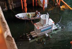
All tests on the subsea transformer were completed successfully in 2012 in the Trondheim pressure laboratory as well as in Trondheim harbor (shallow-water test), with results confirming that this is a market-ready product suitable for a wide power range (typically from 1 to 100 MVA) and for operation in water depths of down to 3,000 m (9,842 ft), says Siemens. Features of the transformer include an enhanced insulation system; a robust enclosure design with optimized natural cooling properties; biodegradable MIDEL 7131 fluid filling; flexible interfaces (dry or wet-mate conditions); and advanced condition monitoring (oil properties, temperature, pressure, ground fault, and so on).
The subsea switchgear has a modular design, featuring 36-kV, 500-A feeders and vacuum circuit-breakers; an integrated auxiliary supply; main switch in 1-atmosphere system canister; a fluid-filled base module; a pressure-compensated bus bar base section; a industrially proven SIPROTEC protection system; and zero differential pressure at all penetrations to seawater. The design is cascadable to allow more consumers to be configured, via connections to seabed templates.
Finally, the variable-frequency drives (VSDs) are also of a modular and pressure-compensated design said to achieve 100% natural convection cooling via dielectric fluid. Internal temperature variations cause fluid to flow, generating the cooling effect.
The VSD prototype will be completed and qualified next year prior to the fully integrated shallow-water trials. "This is probably the most challenging of the three power units to qualify for operation in 3,000 m water depth," Rasch added. "It incorporates a scalable, multi-cell topology, meaning that it comprises many smaller 'building blocks,' or power cells. The number of building blocks is determined by the voltage rating of the unit. Redundancy can be built into the design by including more power cells than needed for the specified rating. If a power cell should fail, the advanced cell bypass function would bypass the power cell (i.e. remove it from the VSD power circuit), allowing the VSD to run with the remaining cells."
Rasch noted that there are other advantages in the multi-cell design with respect to harmonics. "A basic property of frequency converters is that they change the voltage in discrete steps. The output voltage consists of contributions from each of the power cells, and with a large number of cells, the total voltage can be changed in many discrete steps. By incorporating many small discrete steps in the output voltage waveform, we can achieve an almost sinusoidal output voltage with a low harmonic content. Furthermore, the number of cells, combined with a uniquely designed input transformer, cancels out most of the critical harmonic feedback to the supply – the result is low harmonics both to the motor and to the supplying grid."
Following the completion of pressure testing of the various components and subassemblies in the Trondheim lab (around the turn of this year), next year's planned test and qualification procedure is as follows:
- Module testing in a dry environment in assembly factory in Trondheim
- System integration and functional testing in assembly factory
- Shallow-water test and qualification of the switchgear prototype (currently being assembled in Trondheim, testing/qualification in 2015) and the VSD prototype (assembly and testing/qualification in 2015 in Trondheim)
- Shallow-water test and qualification of the power communications and control system
- Shallow-water test and qualification of the completed subsea power grid, including switchgear, VSD, transformer, and respective connections.
